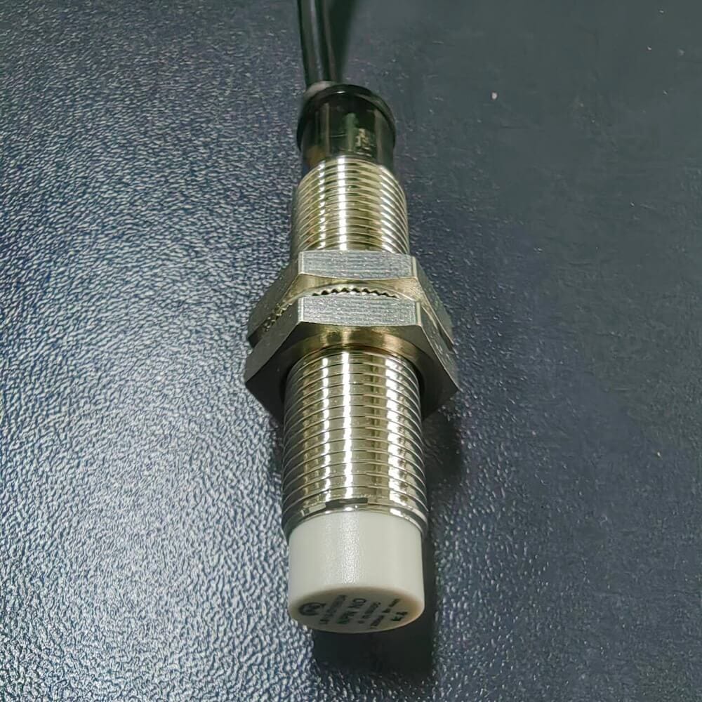
Proximity switches are non-contact position sensors that output control signals once targets reach the effective sensing distance. Thanks to stable performance, strong anti-interference, waterproof and corrosion-resistant features, they are widely adopted in automated production lines.
1. Common Classification of Proximity Switches
- By supply voltage: Divided into AC and DC types. DC24V is the most popular in industrial fields with a wide working range of 10~36VDC. Common AC specifications include 24V, 110V and 220V.
- By working principle
- Inductive type: Detects metal only via alternating magnetic field and eddy current change on metal surfaces.
- Capacitive type: Triggers signals by capacitance variation; compatible with metal, plastic, liquid and glass but vulnerable to nearby metal interference.
- Hall type: Identifies magnetic objects based on magnetic field induction of Hall components.
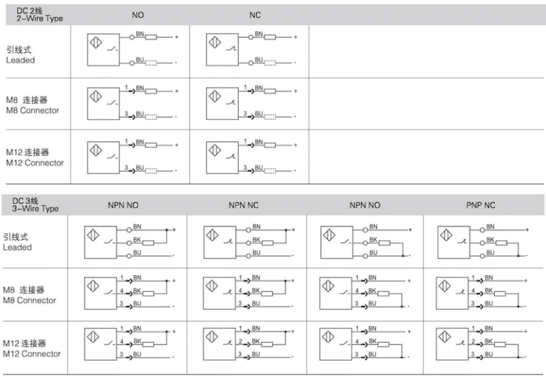
- By wire quantity
- 2-wire: Integrates power and control circuit with inherent leakage current at standby status.
- 3-wire: Two power cables plus one signal output wire, available in NPN and PNP versions.
- 4-wire /5-wire: Independent power loop; 4-wire for single NO or NC, 5-wire for both NO & NC, seldom used on-site.
- By output mode: Transistor(NPN/PNP), thyristor and relay output. 3-wire mostly uses transistor, 2-wire adopts thyristor, multi-wire matches relay output.
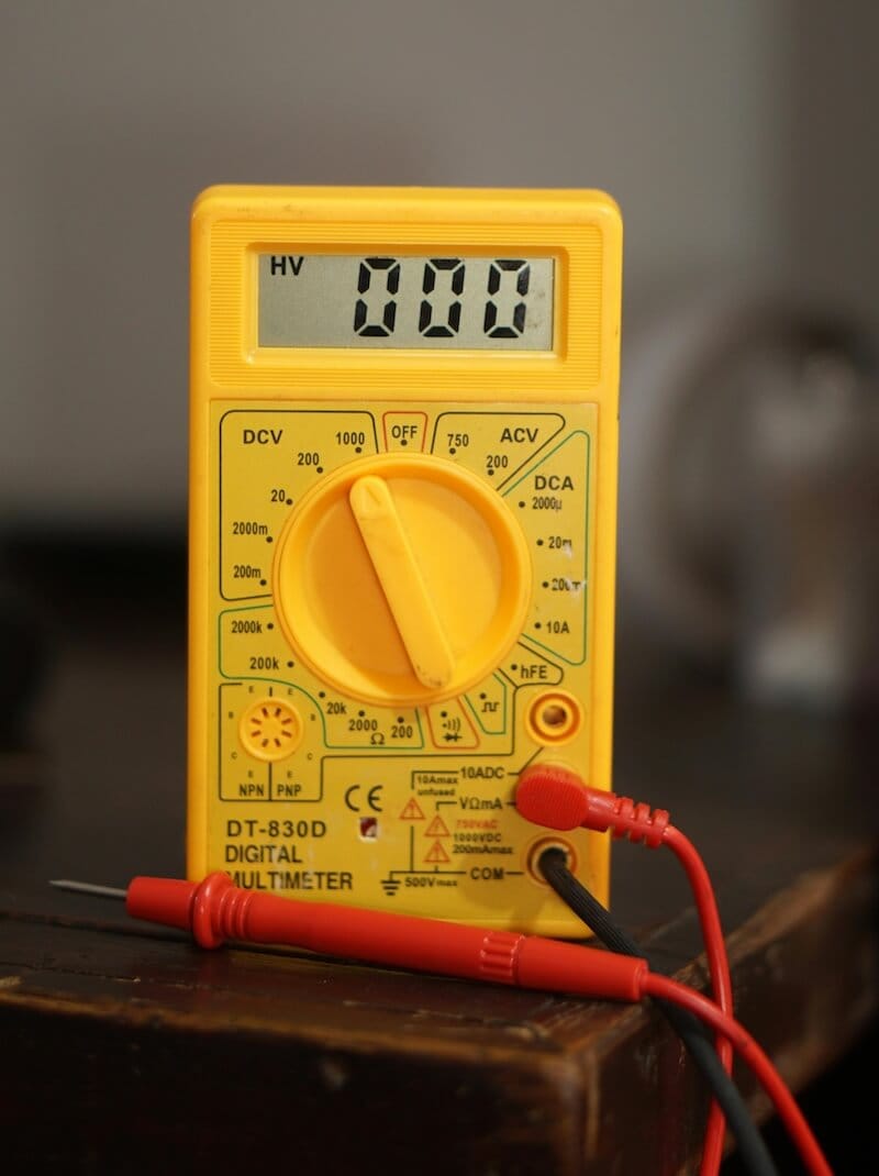
2. Step-by-step Multimeter Testing Guide
Check peripheral wiring and loads first instead of removing the sensor directly when troubleshooting. Start testing only after eliminating external faults.
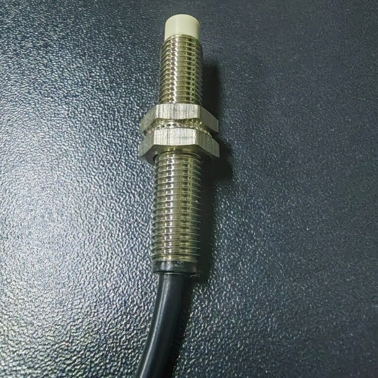
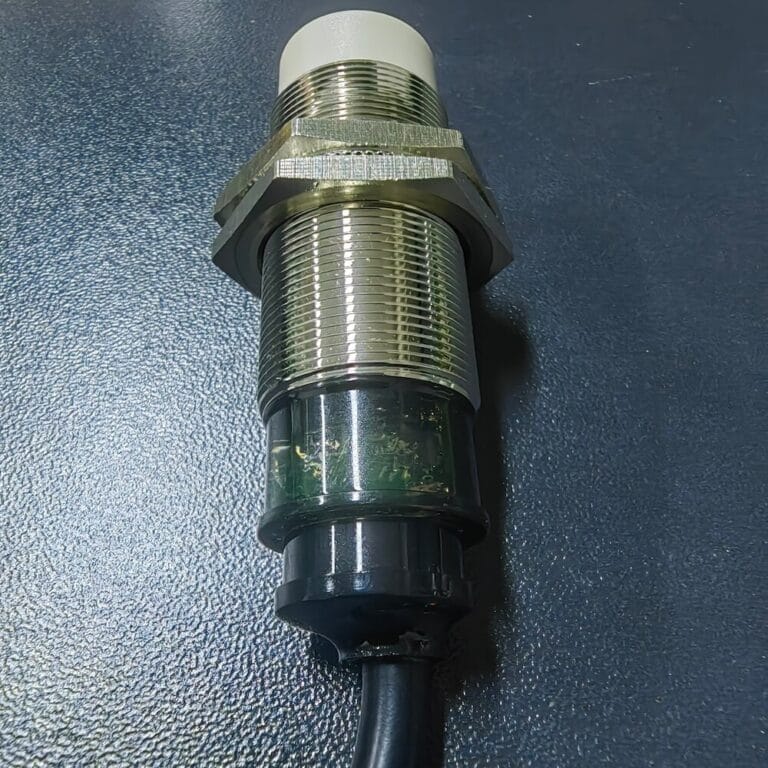
- Preliminary inspection: Check shell damage and indicator light status, confirm fault details from field operators.
- In-circuit live test: Measure input power voltage first. Digital multimeters have high internal resistance which may show false voltage readings. Only test supply and output voltage on-site; resistance measurement is unreliable due to parallel connected components.
- Off-line power-on test (most reliable): Power the sensor with rated voltage separately, put matched targets close to sensing face and test output voltage with multimeter:
- PNP: Red probe on signal output, black probe on 0V; high voltage generates when target approaches.
- NPN: Red probe on positive power, black probe on signal line; voltage drops when target approaches.
- Standard wiring rule: Brown = Positive, Blue = Negative, Black = Signal output. For irregular wire colors, confirm power poles first, the remaining wire is the signal cable.
Interesting to see how a multimeter can test proximity switches. Did you find any specific tips that made the testing easier?
Yes! The easiest tip is to test it with off-line independent power supply.Also, you can quickly distinguish NPN and PNP types by checking the voltage change with a multimeter, which makes field troubleshooting much faster.