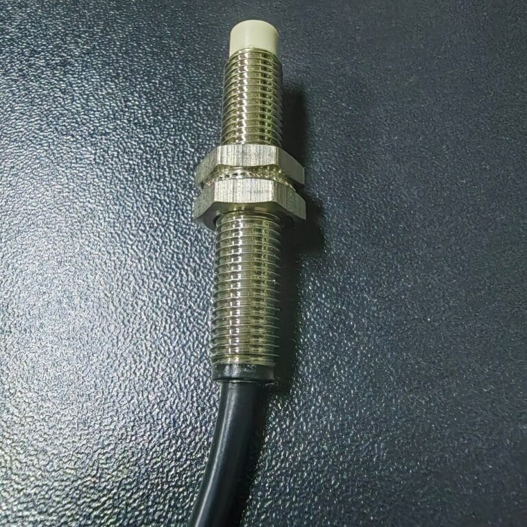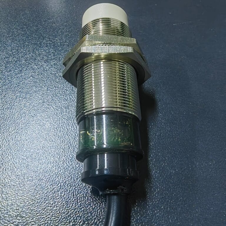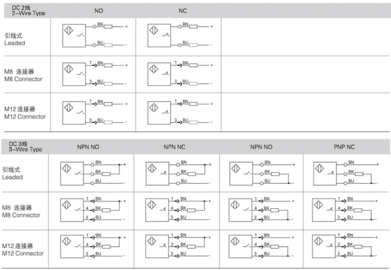

Many maintenance technicians and automation engineers often receive unmarked inductive proximity sensors without datasheets, making it impossible to confirm whether the unit is PNP NO or NPN NC before wiring to PLCs and equipment. Incorrect matching of output types will lead to signal failure, equipment misoperation, and even circuit burnout. This article shares two practical testing methods using a DC power supply, multimeter and transistor tester to accurately judge the sensor output mode.
Standard Wiring Definition for 3-Wire DC Inductive Sensors
Nearly all industrial 3-wire proximity switches follow unified color coding:
- Brown wire: Positive power supply (VCC +)
- Blue wire: Ground / negative power supply (GND -)
- Black wire: Signal output load line
We only need to test the voltage change of the black signal wire under triggered and non-triggered states to initially narrow down the output type range.
Step 1: Voltage Test with 9V DC Power Supply & Multimeter
- Connect the sensor to a 9V battery: brown to positive, blue to negative, leave the black signal wire free for measurement.
- Switch the multimeter to DC voltage mode, attach the red probe to the black signal wire.
- Record two sets of voltage readings:
- No metal target (sensor not triggered): Black vs blue = 0V; Black vs brown = -9V
- Metal target close to sensing face (sensor triggered): Black vs blue = 9V; Black vs brown = 0V
Based on industrial voltage comparison rules, this set of data rules out pure NPN NC and leaves two possible options: PNP NO or NPN NC. We need further diode and transistor testing to get the definitive result.
Step 2: Transistor Tester Verification
- First calibrate the transistor tester with a standard discrete PNP transistor to confirm the tester works normally and correctly identifies PNP/NPN pin definitions (Collector / Base / Emitter).
- Connect the three wires of the proximity sensor to the tester and run the detection cycle. The tester’s indicator light lights up normally during testing, but the final result only displays a single diode characteristic: the black signal wire conducts toward the brown positive wire.
Compare with internal circuit diagrams of PNP and NPN sensors:
- PNP sensor internal transistor: Emitter connects to positive power (brown wire), base controls switching, collector leads to signal output (black wire). The conduction direction of the PN junction points from black signal wire to brown positive wire, matching the test result.
- NPN sensor internal transistor: Base points outward to the positive power side, and the conduction direction cannot form the diode reading tested above.
This test proves the internal switching tube of the sensor is PNP type.
Step 3: Diode Mode Multimeter Secondary Confirmation
Set the multimeter to diode test mode, red probe fixed on the black signal wire, and record three groups of readings under different states:
- Sensor powered by 9V battery, no target detected: Reading = 766
- Sensor powered by 9V battery, metal target triggered: Reading = 0
- Sensor fully disconnected from power supply: Reading = 1128
The diode conduction law further verifies the internal PNP transistor structure:
- When triggered, the PNP tube turns on, the signal wire is directly connected to positive voltage, and the diode test shows near-zero conduction value.
- When not triggered, the tube cuts off, only the internal protective diode forms a weak conduction loop, showing a medium voltage drop value.
- Without external power supply, only the built-in reverse protection diode works, presenting a larger voltage drop reading.
Final Conclusion of Sensor Output Type
Combining three layers of test data (DC voltage test, transistor tester identification, multimeter diode measurement): This unmarked inductive proximity sensor is confirmed as a PNP Normally Open (PNP NO) model.
Practical Tips for Output Matching
- PNP NO sensors are widely compatible with European PLC brands (Siemens, Schneider). The PLC common terminal needs to connect to 0V GND to receive high-level signals when the sensor detects metal.
- If you need to replace old sensors on production lines, confirm the original equipment’s PLC input type first: European systems prioritize PNP, Japanese systems (Mitsubishi, Omron) mostly use NPN output.
- HongSton full-series inductive proximity sensors including miniature LS5 M5 models support optional PNP/NPN and NO/NC modes, with IP67 metal housing, stable anti-interference performance, and complete matching for mainstream automation equipment. All models comply with IEC60947-5-2 industrial standards, available for direct replacement of imported brand sensors.