1. Magnetic Switches
A magnetic switch is a magnet-sensitive proximity switch, widely used to check if cylinders reach the designated position in automation systems. It is divided into contact and non-contact types. Built around a reed switch, it closes the circuit when the magnetic ring on the cylinder approaches, and resets to cut off the circuit once the magnetic field disappears.
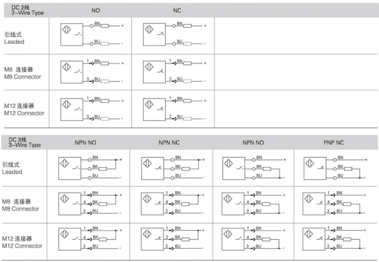
Wiring Types & Connections
Magnetic switches are available in 2-wire and 3-wire designs. The 2-wire type has no NPN or PNP distinction. For low-level control, connect the blue wire to 0V and the brown wire to the load. For high-level control, connect the brown wire to 24V and the blue wire to the load. The 3-wire type includes NPN (low-level output) and PNP (high-level output) versions for different control circuits.
Usage & Wiring Notes
- Incorrect wiring polarity of 2-wire switches will cause the indicator light to fail.
- The maximum working current is 100mA. Do not drive solenoid valves directly. It is recommended to use an intermediate relay, or connect the switch to PLC input terminals.
- A load must be connected in series with 2-wire switches, otherwise the device will burn out.
- Series connection of multiple 2-wire switches leads to voltage drop; it is advised to connect no more than 4 units. Parallel connection increases leakage current and may trigger false operation.
- The leakage current of 2-wire switches is below 1mA, while that of 3-wire types is less than 100uA. 3-wire magnetic switches deliver better stability.
- Its standard sensing range is 8-12mm, not suitable for high-precision positioning. Keep it away from strong magnetic fields. The distance between two parallel cylinders with magnetic switches should be over 40mm to avoid interference.
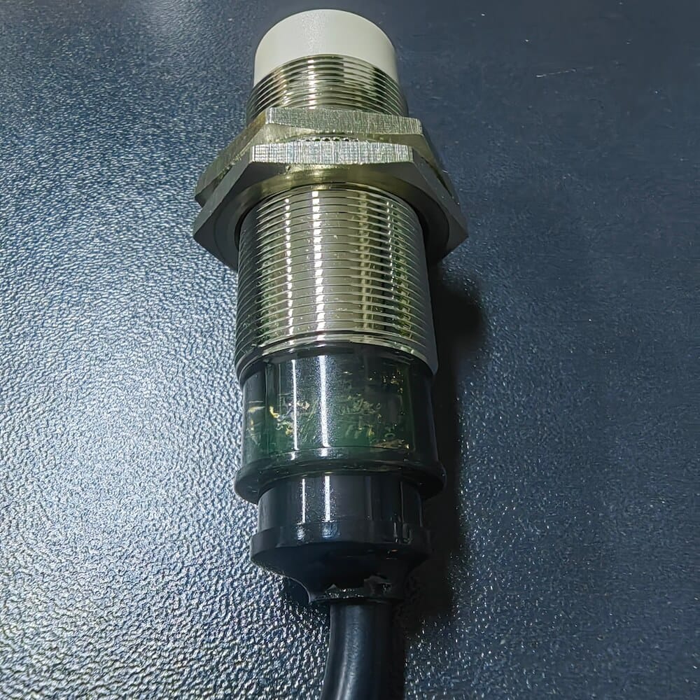
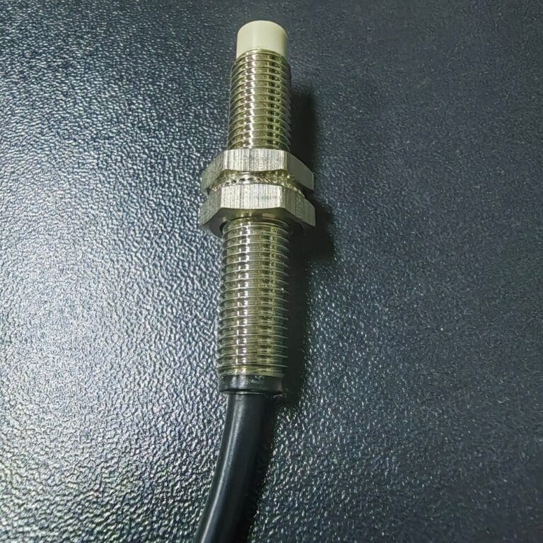
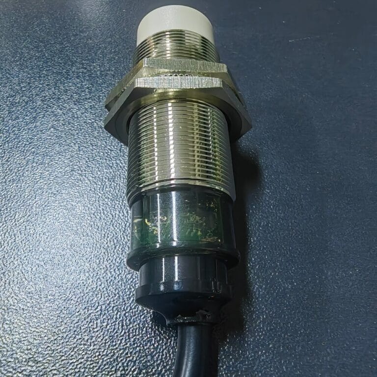
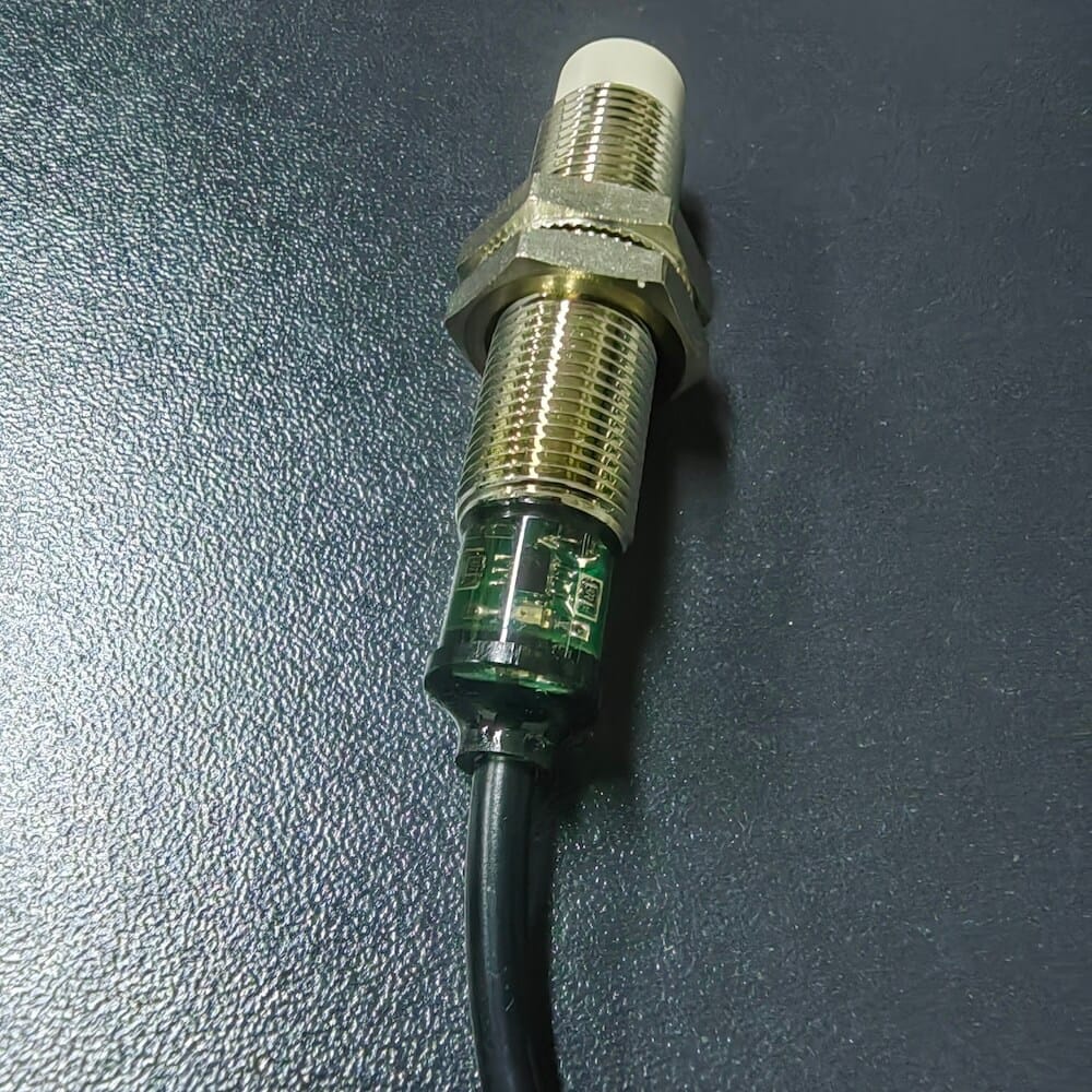
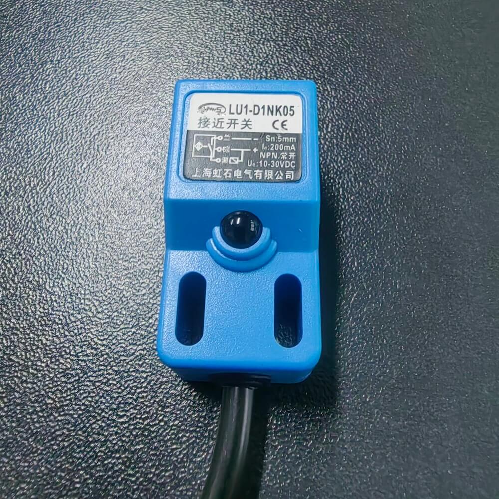
2. Proximity Switches
Proximity switches detect moving objects and output signals, consisting of sensing heads and oscillation circuits. Common types include inductive, capacitive and magnetic proximity switches.
- Inductive type: Equipped with inductive coils, it only detects metal objects. Its sensing performance and distance will decrease greatly when used for copper, aluminum and stainless steel. It works based on alternating magnetic field changes.
- Capacitive type: It operates by capacitance variation. It can detect metals, non-metals, liquids, paper and glass. The sensing distance varies for different targets.
- Magnetic type: Adopts the Hall effect and is designed for magnetic object detection.
Selection & Operation Tips
Choose inductive switches for metal detection, capacitive ones for non-metal detection, and magnetic types for magnetic targets. Select NPN or PNP output according to control circuits, and ensure the load current does not exceed the rated value. DC models feature higher response frequency. Confirm rated voltage before wiring. There are flush and non-flush mounting styles; non-flush installation provides longer sensing distance. Check if mounting nuts are included before purchase.
3. Photoelectric Switches
Photoelectric switches detect objects via light blocking or reflection. Composed of transmitters and receivers, they can only identify opaque objects and are extensively applied in automation.
- Through-beam type: Separate transmitter and receiver. The maximum sensing distance reaches 50m, with strong dust resistance and anti-interference ability.
- Diffuse-reflective type: Transmitter and receiver are integrated. The typical sensing distance is around 3m.
- Retro-reflective type: Matched with a reflector. Effective sensing distance ranges from 0.1m to 20m with high reliability.
- Slot type: U-shaped structure. It can detect high-speed moving objects and semi-transparent items. Some models support switching between NO and NC output.
- Fiber optic sensors: Used together with amplifiers. They offer high precision for tiny object detection and are applied in high-accuracy scenarios.
Keep photoelectric switches away from water, oil, heavy dust and direct strong sunlight for stable operation.
4. General Electrical Parameters & Wire Color Codes
- Specifications: Operating voltage 12-30VDC, current consumption <15mA. Built-in reverse polarity, short circuit and overload protection. Standard sensing distance: 10mm (±10%). Response frequency: 500Hz (DC). Operating temperature: -40℃ ~ 85℃.
- Wire codes: BN (Brown) = 24V positive, BU (Blue) = 0V, BK (Black) = Signal output, WH (White), GR (Grey).
5. Application Case
After powering on, the proximity switch is triggered by a nearby object. Relays act sequentially and form a self-locking circuit to keep the indicator light on. The circuit remains connected even if the object moves away. The light turns off only after cutting off the main power.