When selecting and installing proximity switches for industrial control systems, it is essential to distinguish between NPN and PNP output types, which determines whether the sensor can work properly with PLCs, relays and other equipment. Except for 2-wire AC models, most DC proximity switches adopt open-collector output. They are mainly equipped with three core wires: VCC for positive power, GND for negative power and OUT for signal output. Some 4-wire versions provide both normally open and normally closed signals at the same time.
1. Wire Definition & Basic Introduction
Standard wire color rules: Brown or red wires connect to VCC (positive power), blue wires connect to GND (negative power), and black or white wires serve as the OUT signal line.
- NPN type: It outputs negative voltage. Internally, the signal terminal is connected to the power negative pole.
- PNP type: It outputs positive voltage. Internally, the signal terminal is connected to the power positive pole.
Both types have Normally Open (NO) and Normally Closed (NC) versions. You need to take the output status into consideration during selection.
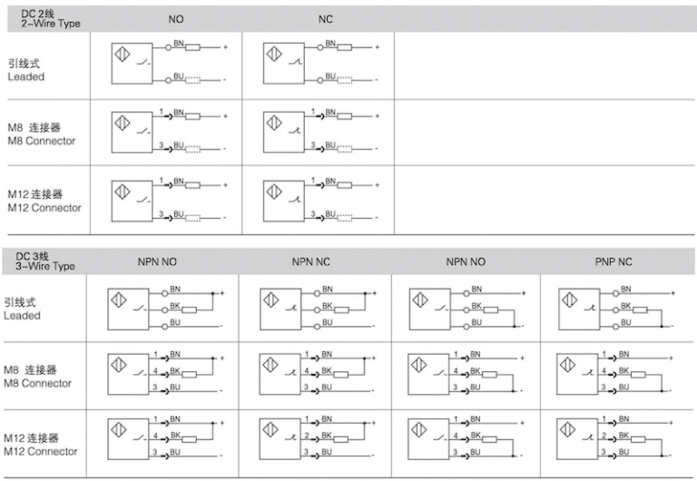
2. Common Wiring Types
Proximity switches used in industrial applications fall into three categories: 2-wire, 3-wire and 4-wire.
- 2-wire type: Available in AC and DC versions with NO and NC options. Simply connect the sensor and load in series to the power supply.
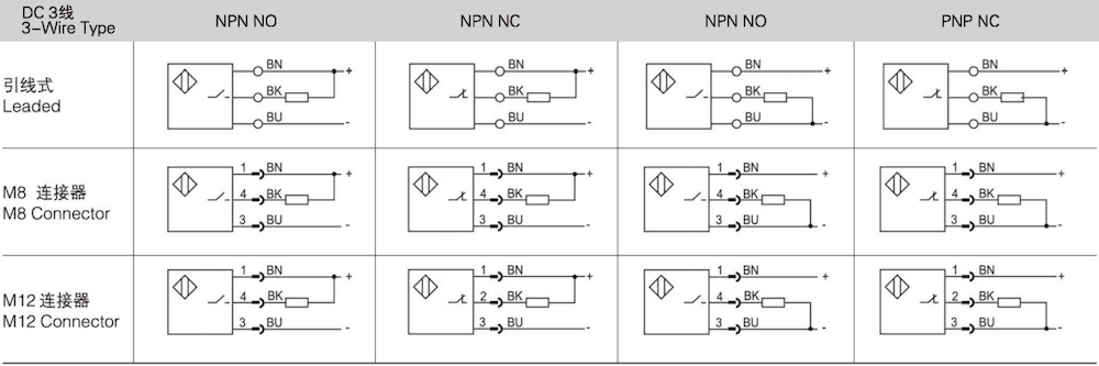
- 3-wire type: Including NPN-NO, NPN-NC, PNP-NO and PNP-NC. It is the most widely used type in automated equipment.
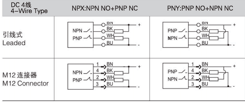
- 4-wire type: Supports simultaneous NO and NC signal output, also divided into NPN and PNP types.
Working Principles
- NPN type: The common terminal connects to power negative pole and outputs low level when triggered. For NO models, the signal line stays disconnected without detection and connects to GND after being triggered. NC models work in the opposite way.
- PNP type: The common terminal connects to power positive pole and outputs high level when triggered. For NO models, the signal line stays disconnected without detection and connects to VCC after being triggered. NC models work in the opposite way.
For PLC connection, Japanese-brand PLCs generally use positive common terminals and match NPN sensors, while European PLCs adopt negative common terminals and fit PNP sensors. Some modern PLCs support switchable common terminals for flexible matching. Note that Siemens and Mitsubishi define input modes differently, so please check carefully before wiring.
3. Key Differences Between NPN and PNP
- For standard 3-wire wiring, brown wire connects to positive power and blue wire connects to negative power. The load of NPN sensors links to positive power, while the load of PNP sensors links to negative power, leading to opposite current directions.
- Applicable loads include indicator lights, relays and PLC digital input modules. Always select the right sensor according to the PLC standard; incorrect matching will cause equipment failure.
- In terms of performance: 2-wire switches feature simple wiring but have voltage drop and residual current issues. 3-wire switches deliver better stability and anti-interference performance, ideal for high-precision working conditions.